
Search Results:
Search Results:
Search Results:
Search Results:
Find the best active & neutral links red & black here at Sparky Direct. [ Read More ]
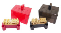
An active and neutral link is a brass or tinned-copper bar drilled with multiple terminal holes, mounted inside a coloured plastic housing, and fitted with screws that clamp incoming and outgoing conductors. Both link types perform the same mechanical job: they consolidate many smaller conductors into a single, low-resistance termination point. The functional difference is which side of the supply they connect to.
The active link takes the active (live) conductor from the main switch or upstream protective device and distributes it across multiple sub-circuits. Each circuit breaker on the board draws its incoming active feed from this link. Current flows from the supply, into the active bar, through each breaker, then out to the load. Because the active conductor carries full mains potential, the link must be enclosed and clearly identified to prevent accidental contact.
The neutral link provides the return path for current back to the supply transformer. Every sub-circuit terminates its neutral conductor on this bar. In a standard MEN (Multiple Earthed Neutral) installation, the neutral link at the main switchboard is also bonded to earth at one specific point. The neutral bar is the reference point for all return current on the installation.
A circuit only works when both conductors are intact. Current must leave through the active and return through the neutral. If either link develops a fault, loose terminal, or burnt connection, the entire circuit becomes unreliable or unsafe. The pairing of an isolated neutral link with a separate active link allows electricians to test, isolate, and reconnect each side independently during fault-finding.
Inside a domestic, commercial, or industrial board, active and neutral links sit alongside the main switch, RCDs, and circuit breakers. They are the connection points where field cables meet the protective devices.
A single incoming active conductor from the supply may need to feed ten or more sub-circuits. Without a distribution link, every breaker would require its own direct tap to the main switch, which is impractical. The link provides a single bus point with multiple terminal holes, keeping wiring tidy and serviceable. The same logic applies to the neutral side, where every load circuit returns to one common neutral bar inside the electric switchboard.
In three-phase boards, neutral current depends on how loads are spread across phases. A well-terminated neutral link ensures the unbalanced return current has a low-resistance path back to the supply. Loose or undersized terminations cause heating, voltage drift, and premature failure of equipment.
Modern installations often use isolated neutral links per circuit, where each circuit's neutral lands on its own dedicated terminal. This lets the electrician disconnect a single neutral for testing without affecting other circuits. It also makes RCD testing accurate, because each protected circuit's neutral can be confirmed in isolation.
The red and black colour scheme on these links is a long-standing Australian convention. The colours identify the function of the bar at a glance, before any conductor is even traced.
Under historical Australian wiring practice, red sheath or insulation indicated active and black indicated neutral. Link housings followed the same coding: a red plastic body for the active bar, a black plastic body for the neutral bar. This visual rule is still applied to switchboard links today because legacy installations and existing meter boxes use the same convention.
Modern flexible cables and many newer installations now use brown for active and blue for neutral, in line with international harmonisation. However, fixed wiring inside Australian switchboards typically still uses the older red/black sheathing on TPS and building wire. Mixed installations are common, especially in homes that have been progressively upgraded. Always treat colour as a starting point, not a guarantee.
Coloured links help prevent the most common switchboard mistake: connecting an active conductor to a neutral terminal. A red housing visually warns the electrician that the bar is live whenever the main switch is on, while a black housing flags a current-carrying return path. Combined with proper labelling, the colour system reduces the cognitive load during a busy installation.
AS/NZS 3000:2018 (the Wiring Rules) requires positive identification of active and neutral conductors. Colour coding alone is not sufficient verification: testing with a calibrated voltage indicator is mandatory before any conductor is touched.
Switchboards fail in predictable ways when links are poorly chosen, poorly terminated, or wrongly identified. The consequences range from inconvenient to life-threatening.
A reversed connection, where active is landed on a neutral bar, energises every chassis bonded to that neutral. This can deliver a fatal shock through any earthed appliance. Loose terminations cause arcing inside the housing, which can ignite the plastic enclosure and surrounding insulation. A 240V arc fault releases enough energy to start a fire inside a meter box within seconds.
Cross-connecting circuits between active and neutral links creates parallel paths and unbalanced loads. RCDs see neutral current that does not match active current and trip nuisance, or worse, fail to trip on a real fault. Miswiring also defeats correct breaker coordination, leaving downstream circuits unprotected.
Every conductor must be confirmed with a voltage tester or multimeter before termination. Colour coding tells you what the conductor was intended to be, not what it actually is. In renovation work, especially, previous tradespeople may have substituted conductors of the wrong colour, and the next electrician inherits the mistake unless they test.
Always test before you trust: Treat every conductor as live until proven dead with a calibrated tester. Never rely on the position, colour, or label of a conductor without confirmation.
Although the bars look similar inside their housings, the active and neutral links serve very different roles in circuit operation.
| Feature | Active Link (Red) | Neutral Link (Black) |
|---|---|---|
| Conductor type | Live (carries supply potential) | Return (carries return current) |
| Housing colour | Red | Black |
| Typical position on board | Above or beside circuit breakers | Below or alongside the active link |
| Switching | Switched by main switch and breakers | Generally not switched in standard circuits |
| Earthing | Never bonded to earth | Bonded to earth at MEN point only |
| Fault current | Carries fault current to protective device | Carries imbalance current to RCD |
The active conductor is the source of energy for any load. Switching the active opens the circuit and stops current flow. The neutral, by contrast, completes the path back to source. In a properly designed circuit, the neutral sits at near-earth potential during normal operation.
Australian Wiring Rules require that switching disconnects the active conductor. A light switch breaks the active feeding the lamp, leaving the neutral connected. This is why a lamp can still give a shock through a faulty switch even when turned off, if the active and neutral are reversed somewhere in the circuit.
A broken or high-resistance neutral causes voltage swings on the load side. In three-phase systems, a lost neutral can push 415V across single-phase appliances designed for 230V. This destroys equipment and creates a real shock hazard. The neutral link's terminal integrity is therefore not optional, it is foundational to the safety of every connected device.
Active and neutral links appear in almost every switchboard, sub-board, and distribution panel installed in Australia. The application dictates the size, current rating, and number of terminals required.
Lighting circuits typically draw modest current, so smaller 5-hole or 7-hole links handle the active distribution. Multiple lighting sub-circuits land on one neutral bar, with each circuit's RCD or RCBO maintaining isolation. The compact link footprint suits residential boards where space is tight.
Power circuits drawing higher current need links rated for the cumulative load. Heavy-duty 13-hole, 165A or 350A links serve large boards with multiple GPO circuits and dedicated appliance feeds. Pair these with appropriately sized building wire to avoid bottlenecks at the termination.
Industrial and commercial distribution boards combine multiple link sets, often segregated per phase or per circuit group. A three-phase board may contain three separate active links (one per phase) plus a single neutral link sized for unbalanced load. Specialised insulated busbars are an alternative when very high terminal counts are needed: see insulated busbars in pin and fork shape for high-density applications.
The right link depends on the size of the board, the number of circuits, the largest conductor that needs to terminate, and the available space inside the enclosure.
Each terminal hole on a link is sized to accept a specific maximum conductor cross-section. A 5-hole 80A link suits typical residential 2.5mm and 4mm circuits. A 13-hole 165A heavy-duty link accepts much larger conductors for commercial sub-mains. Always check the manufacturer's published terminal capacity against the largest cable you plan to land on the bar.
The conductive bar inside the housing is usually brass or tinned copper. Brass offers good corrosion resistance and adequate conductivity for most installations. Tinned copper has lower resistance and is preferred for high-current applications. The screw terminals should be steel with a clear thread cut: cheap stamped screws strip under proper torque and create loose connections within months.
Many Australian boards are designed around DIN-rail mounting. Check that the link footprint and mounting holes match the rail spacing in your enclosure. For modular boards with combs and busbars, links from brands such as NLS, IPD, and Hager typically follow consistent mounting patterns within their own ranges.
Switchboard work is restricted to licensed electricians under the Wiring Rules. The procedures below summarise the safe sequence for working on a board where active and neutral links are being installed or replaced.
Before any work begins, the supply must be isolated at the main switch and confirmed dead. For consumer mains work upstream of the main switch, isolation by the supply authority may be required. Apply lockout kits and lockout tags to prevent re-energisation. Verify the dead state with a tested voltage indicator on every conductor you intend to touch.
The proven sequence is test-on-known-live, test-the-conductor, then test-on-known-live again to confirm the tester still works. This catches a faulty tester before it gives a false dead reading. Insulation testers are then used to verify circuit integrity before re-energisation.
In every Australian state and territory, switchboard installation, alteration, and replacement is restricted electrical work. A licensed electrician must perform the work, and a Certificate of Compliance or equivalent must be issued. DIY work on switchboards is illegal regardless of the homeowner's competence.
Safety First: Never assume a circuit is dead because the breaker is off. Always test, lock out, and tag out. The few minutes spent on isolation are the difference between a routine job and a fatal incident.
Active and neutral links must comply with the relevant clauses of AS/NZS 3000 and any product-specific standards covering the housing and conductive parts.
AS/NZS 3000:2018 sets out the requirements for conductor identification, termination, and switchboard construction. Key clauses cover mechanical protection of live parts, IP rating of enclosures, and segregation of incoming and outgoing conductors. Links sold for use in Australia must be suitable for the voltage and current of the installation as defined by the standard.
Every termination point on a switchboard must be identifiable. The active link's red housing satisfies part of this requirement, but circuit identification labels on each terminal are also expected for boards with more than a few circuits. Labelling allows the next electrician to find a specific circuit's connection without tracing every conductor.
After installation, the board is verified by visual inspection, polarity testing, earth continuity testing, and insulation resistance testing. The active and neutral links are checked for correct termination, torque, and clearance from earthed parts. A Certificate of Electrical Safety (or state equivalent) confirms the work meets the standard.
Switchboard design has evolved over the past two decades, driven by safety standards, modular hardware, and the rise of solar and battery installations.
Newer installations increasingly use brown for active and blue for neutral on flexible cables, matching IEC harmonised colours. Fixed building wire in Australia still commonly uses red and black, but the active and neutral link housings continue to use the traditional red and black coding regardless of cable colour. The housing colour identifies the function of the bar, not the cable colour landing on it.
Heat-shrink markers, printed circuit labels, and engraved cover plates are now standard on commercial boards. Each circuit's active and neutral terminations carry a matching reference number, allowing rapid identification during fault-finding or alteration. Red electrical tape and black electrical tape are also used to flag re-purposed conductors that no longer carry their original colour.
Renovations often expose older red/black wiring sitting next to newer brown/blue flexibles. The safest approach is to terminate each conductor based on tested function rather than colour, then add identification tape or markers at the termination so future technicians can follow the actual circuit. Mixed installations also benefit from clear circuit schedules inside the board cover.
Active and neutral links are mostly maintenance-free, but they sit at the heart of every fault-finding exercise. Knowing how to test them quickly speeds up diagnosis on any board.
Active link faults often present as a tripping breaker, a discoloured terminal, or a buzzing sound at the housing. Visual inspection during a planned shutdown is the first step: look for blackened plastic, melted insulation around the conductor, or screw heads that have lost their torque marks. Thermal imaging during normal operation can pinpoint hot terminations before they fail.
A failing neutral link is harder to spot because the bar carries return current rather than supply. Symptoms include dim lights when heavy loads switch on, equipment damage from voltage swings, and erratic RCD operation. Measuring voltage between neutral terminals and earth at the board reveals a developing fault: a healthy neutral sits within a few volts of earth, while a degraded neutral can show 20V or more.
Mis-diagnosing a link fault as a downstream circuit fault wastes hours and may leave the underlying issue in place. Always start at the link, confirm clean voltage references on both active and neutral, then work outward to individual circuits. A quality multimeter and insulation tester pay for themselves on the first hard fault.
Even experienced electricians fall into a handful of repeating traps when working on links. Watching for them prevents callbacks and protects your customers.
Colour is a starting point, not proof. Old installations, DIY work, and overseas-imported equipment all use different colour conventions. Always confirm with a tester before terminating.
Loose screws are the single most common cause of link failures. The right torque is published by the link manufacturer and should be applied with a calibrated torque screwdriver, not by feel. Over-tightening crushes the conductor and is just as bad as undertightening.
Fast jobs go badly wrong when the main switch is left on. There is no production pressure that justifies live switchboard work. Isolate, lock out, test, and only then begin.
Confirm isolation at the main switch. Apply lockout. Test for dead on every conductor with a verified tester. Re-test the tester on a known live source. Only then remove or modify any link.
Trade-grade links last decades. Cheap imported links can fail within a year, often by stripping screws or melting housings under sustained load. Buying from a reputable supplier protects the installation and the electrician's reputation.
Sparky Direct stocks the full range of electrical accessories, including active and neutral links from established Australian and European brands. Online ordering with fast Australia-wide delivery suits both single-job purchases and bulk stock orders for fit-out work.
The price difference between budget and trade-grade links is small compared to the labour cost of replacement. Brands like Clipsal, Major Tech, and Legrand use harder brass alloys, deeper screw threads, and tougher housings that survive years of repeat torquing. Anonymous imported links often skimp on all three.
Match the terminal hole count to the circuit count, plus a couple of spares for future expansion. Check the current rating against the largest cumulative load. Confirm the housing colour matches your installation's identification scheme. Verify the mounting footprint suits the circuit protection rail or backplate inside the enclosure.
When a board misbehaves, the active and neutral links are the first place to check. Problems here cascade into every connected circuit.
Intermittent loss of supply on one or more circuits often points to a marginal terminal on the active link. Vibration, thermal cycling, or a screw that was never properly torqued can leave a connection that works most of the time and fails under load. Visual inspection during a shutdown, followed by re-torquing every screw, resolves the majority of cases.
Discolouration of the housing, melted plastic around a terminal, or a smell of burning at the board indicates a hot connection. The link should be replaced rather than re-tightened: once the brass has been heat-cycled, the metallurgy is compromised and the connection will not stay tight long term. Use thermal imaging on commercial boards during regular maintenance to catch developing hot spots early.
If circuit testing returns unexpected results, a previous tradesperson may have crossed an active and neutral somewhere upstream. Trace each conductor with a multimeter from the link backward to the consumer device. Add identification tape or markers at every termination once the correct mapping is verified.
Watch NLS 30037 | 5 Hole Neutral Link Black Housing video
Watch NLS 30044 | 12 Hole Active Link Red Housing video
Watch NLS 30290 | Heavy Duty 13 Hole 165Amp 500v Active Link video

Excellent service, arrived quick. It's an earth bar, what can I say? Solid, brass and 2 screw!!! Sparky Direct are competitive and easy to deal with... Go Hard!
Good product, exactly what was described. Paid for express postage. Got it within 3 business days in rural SA as promised.
Well made quality products. Delivery is fantastic now Australia Post is back to it's best performance (paying the $3 for priority). $3 well spent if you are in a hurry.
Quality products in stock • Fast Australia-wide delivery • Competitive trade pricing
Browse Active and Neutral Links → Get Expert Advice →Yes, colour coding improves clarity and reduces the chance of wiring errors.
Sparky Direct supplies active and neutral links in red and black Australia-wide, offering reliable switchboard components with convenient delivery.
They are securely packaged and delivered via standard courier services.
Unused products are generally eligible for return according to the seller’s returns policy.
Warranty coverage varies by manufacturer and typically covers defects in materials or workmanship.
Yes, they are typically sold as individual electrical components.
Yes, correct selection ensures safety, compliance, and reliable performance.
Once installed correctly, they generally require no maintenance.
Yes, they are commonly used when upgrading or modifying switchboards.
Yes, their colours make them easy to identify during installation or maintenance.
Quality links are designed for long-term use in electrical enclosures.
Yes, they help keep wiring organised and neatly terminated.
They are straightforward for licensed electricians to install as part of a compliant system.
Active and neutral links are electrical terminal links used to connect and distribute active (live) and neutral conductors within switchboards and enclosures.
Yes, they are standard components in switchboards and control panels.
They help organise wiring and ensure safe, clear distribution of electrical circuits.
Many links are designed for DIN rail or direct panel mounting.
Yes, colour coding helps electricians quickly identify circuit functions.
Yes, they are available in various sizes to suit different conductor quantities and cable sizes.
They are typically made from conductive metal with insulated mounting bases.
Yes, they are suitable for residential, commercial, and light industrial applications.
Yes, they are used in residential switchboards and electrical enclosures.
Quality links are manufactured to meet relevant AS/NZS electrical and safety standards when installed correctly.
They are commonly used in switchboards, meter boxes, and distribution panels.
Red is commonly used to identify active links, while black is typically used to identify neutral links, aiding clear circuit identification.


